Senior Mechanical Design Engineer

Designing intelligent
medical devices.

Senior Mechanical Design Engineer specializing in medical-device innovation, CFD simulation, product development, and manufacturable systems engineering.

Omid Bafkar
Scroll
MicrofluidicsCFD · FEA · FSISolidWorks · ANSYS ISO 13485DFM · DFMA · DFMEASix Sigma Black Belt Biomedical Devices10+ years MicrofluidicsCFD · FEA · FSISolidWorks · ANSYS ISO 13485DFM · DFMA · DFMEASix Sigma Black Belt Biomedical Devices10+ years
— Services

What I do.

Full-cycle engineering from theoretical concept to compliant, high-volume production.

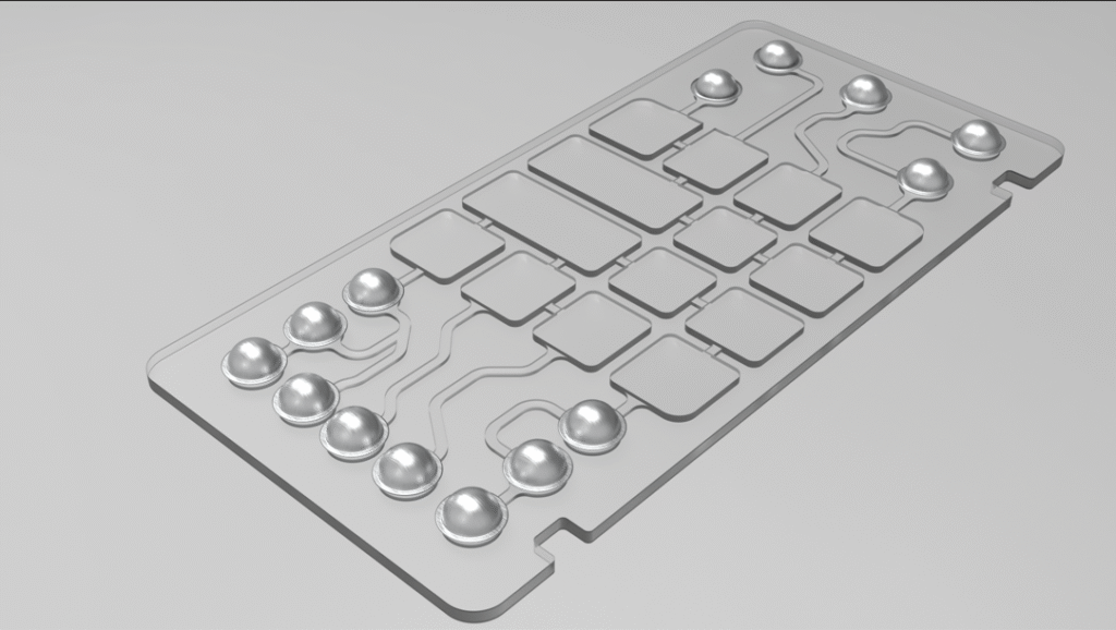
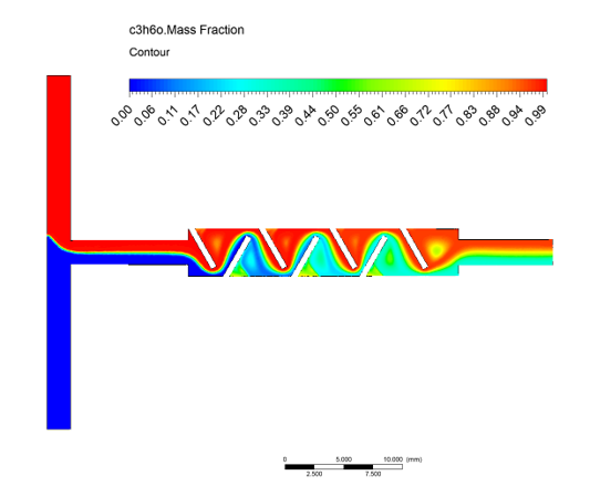
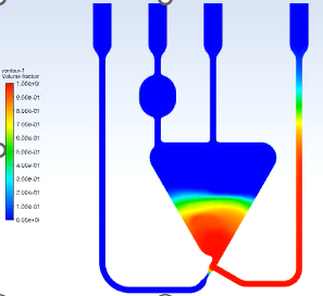
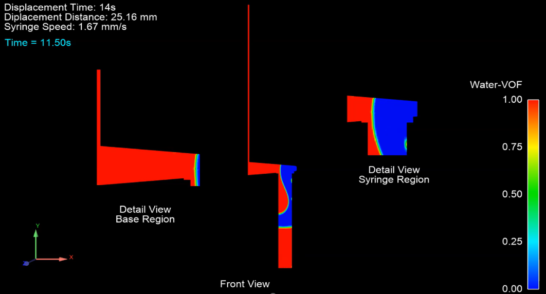
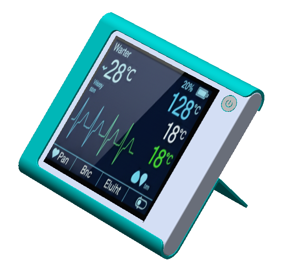
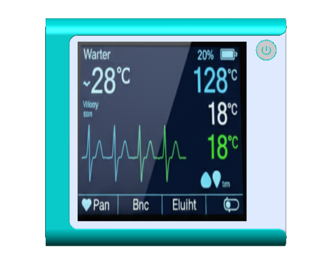
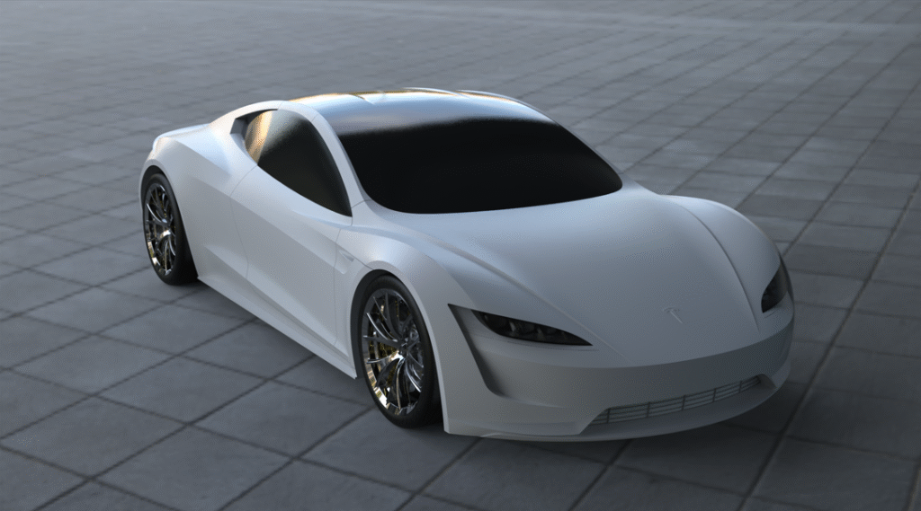
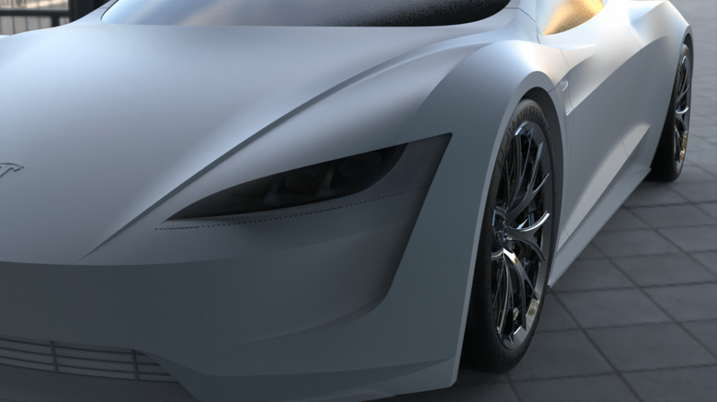
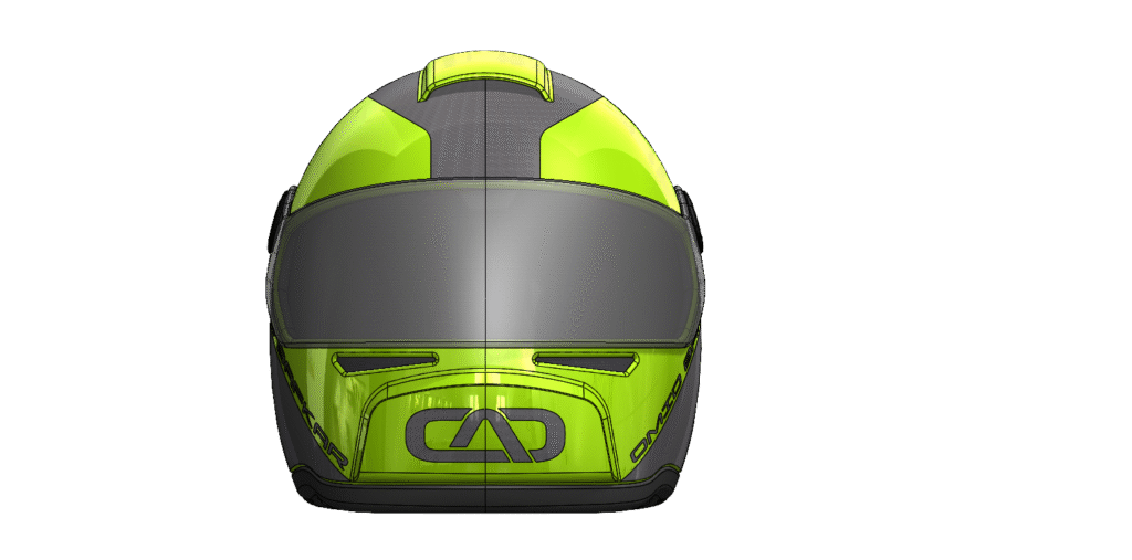
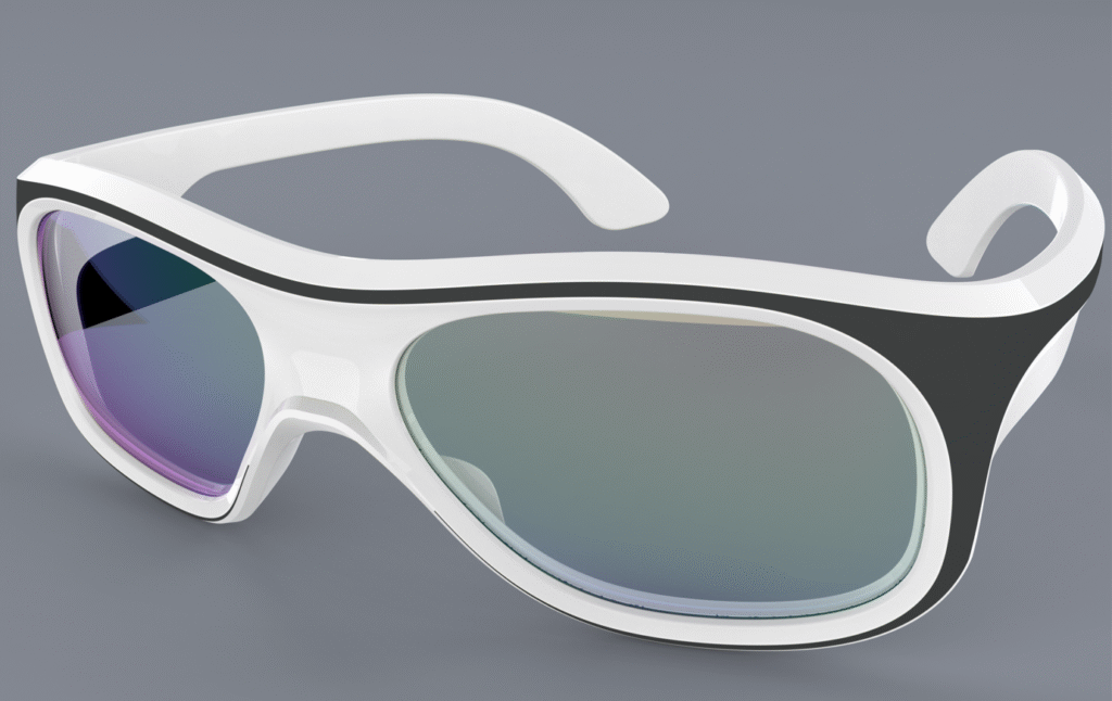
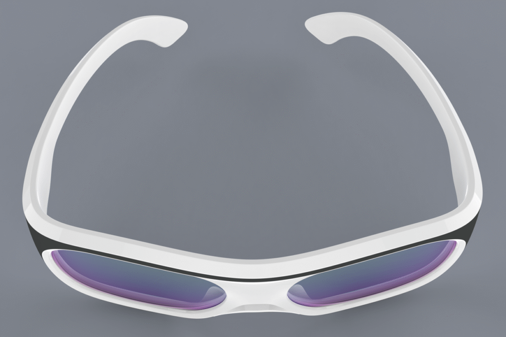
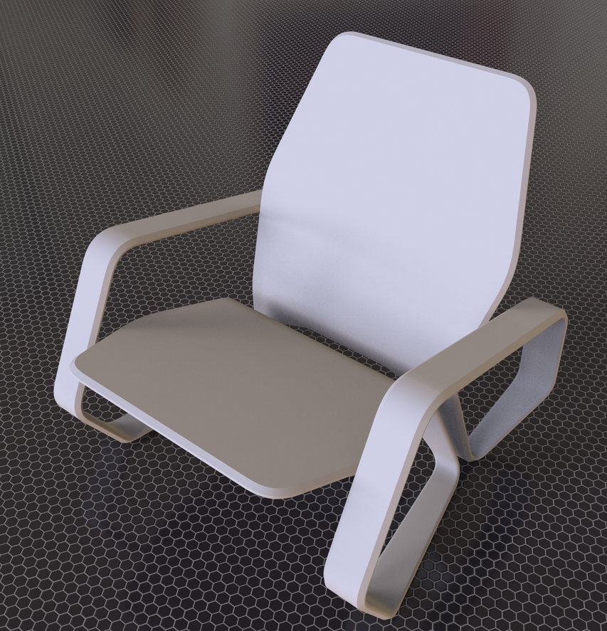
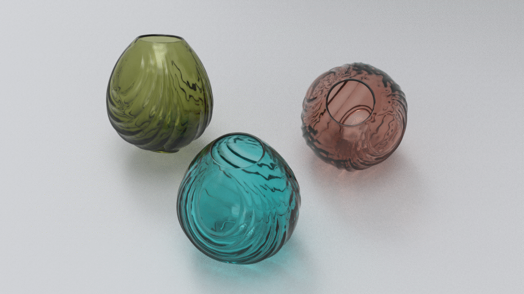
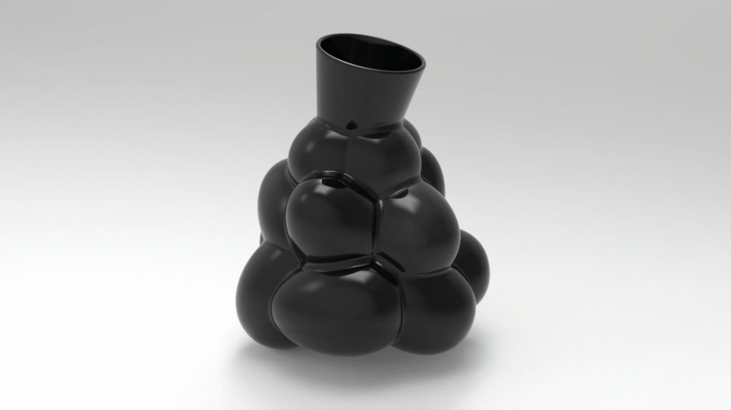
Microfluidic & Complex Mechanism Design

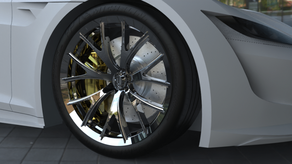
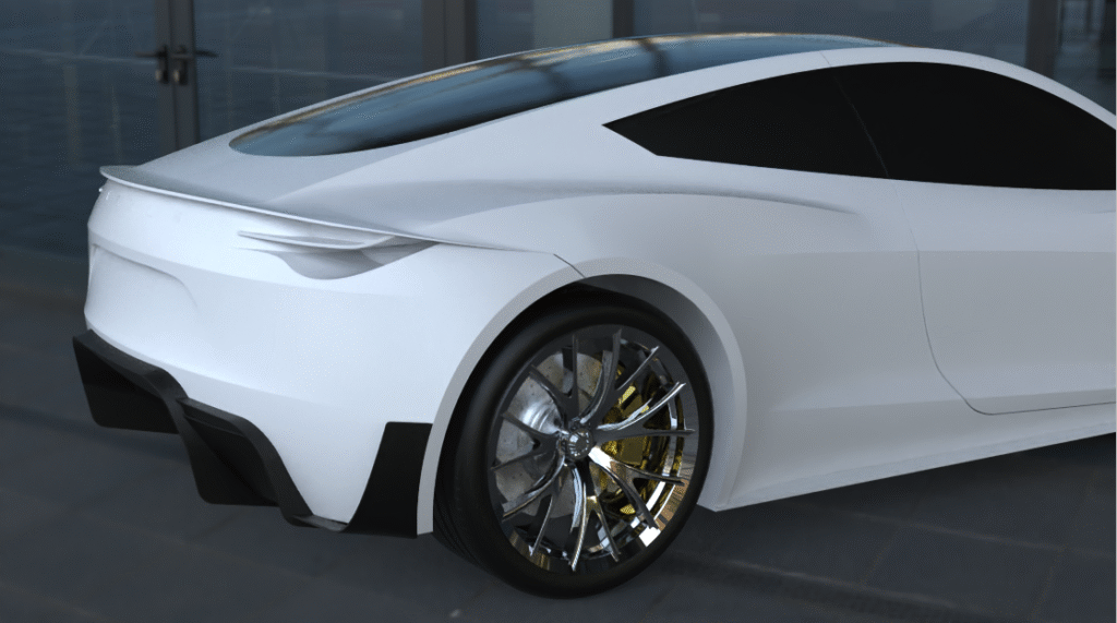
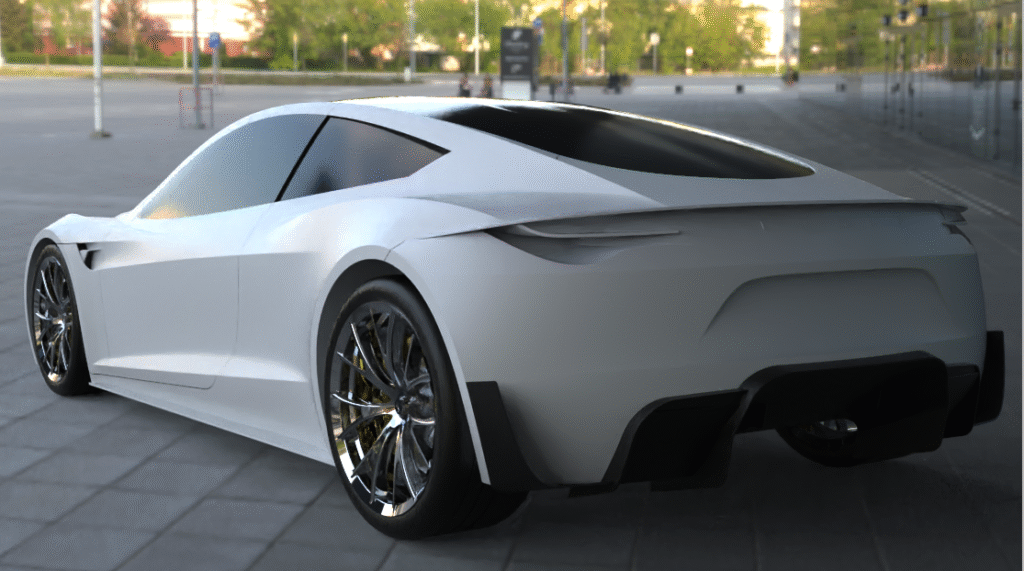
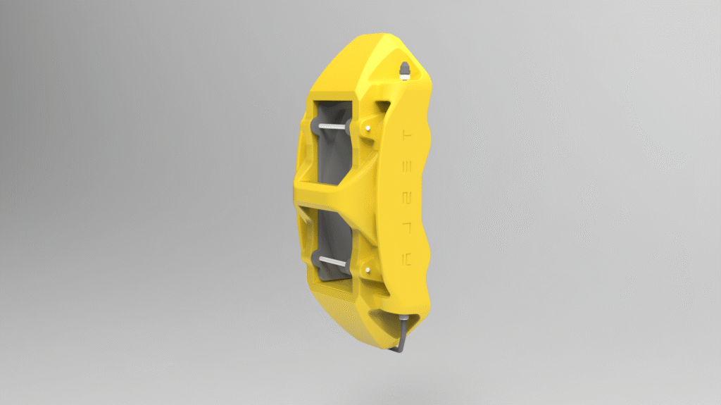
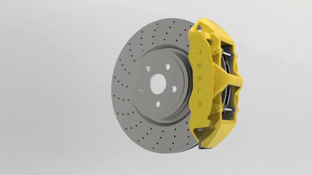
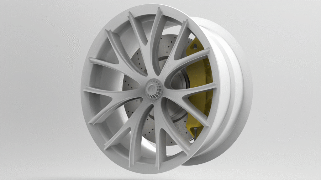
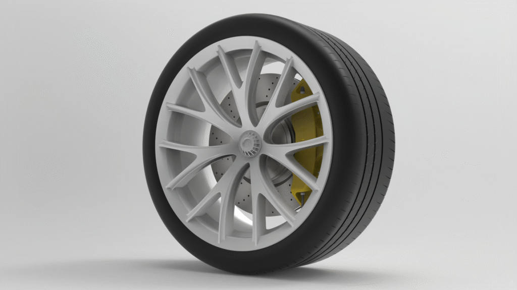
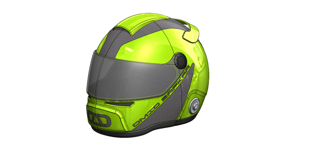
Full-cycle design of electromechanical, thermal, and microfluidic systems. Expertise in 3D CAD (SolidWorks/Fusion 360), Stepper Motor integration, and translating theoretical concepts into high-reliability hardware.

CFD/FEA & Risk-Based Performance Analysis

Applying advanced CFD/FEA to optimize thermal and stress performance. Conducting V&V, FMEA, and Root Cause Analysis to ensure risk-based design compliance and repeatable, real-world reliability.

User-Centric DFX & Production Transfer

Driving innovation from UI/UX workflows and sensory testing through DFM/DFMA. Working with international molding teams for seamless, compliant ISO 13485 design-to-production transfer.

— Measurable Impact

Numbers that matter.

0%
Success rate in design-to-production transfer
$0K
Saved accelerating iterative user testing cycles
0%
Reduction in assembly steps via DFMA integration
— Technical Competencies

The toolset.

SolidWorks90%
ANSYS90%
3D Printing90%
Root Cause Analysis80%
Injection Molding75%
Python65%
Fusion 36060%
DFMEA60%
Tolerance Analysis & GD&T60%
MATLAB50%
— Reviews

In their own words.

"

Outstanding CFD expertise and a true team player. Omid's work was instrumental in driving smart, informed decisions throughout our projects.

Thomas Walsh
Engineering Collaborator
"

Omid's multidisciplinary research and groundbreaking CFD work on sleep apnea are truly impressive and impactful.

Alejandro Vargas-Uscategui
Research Colleague
"

Omid's exceptional FEA and fluidic analysis skills consistently delivered robust solutions and production-ready designs.

Rodney Bucknell
Engineering Manager

Ready to bring your ideas to life?

Open to senior leadership in Biosensor, Microfluidic, or Medical Device R&D where deep mechanical engineering and user-centric design meet. Let's discuss how 10+ years of end-to-end innovation can translate your technical vision into a market-ready product.

R&D Projects

Computational fluid dynamics and biomedical research — patient-specific simulation, surgical training systems, and beyond.

Project 01

Simulation-Based Prediction of Sleep Apnea

Patient-specific CFD/FSI methodology — from MRI acquisition to airway-collapse prediction — that became the basis of U.S. Patent 12,211,209.

Upper airway sagittal CFD schematic
Patient-specific upper-airway geometry from dynamic MRI · k-ω SST turbulence model · OSA collapse study
Upper airway CFD computational domain
CFD computational domain · nasal-inlet velocity BC → pressure outlet · FSI coupling at soft-tissue walls
Upper airway sagittal schematic — CFD domain Structural schematic of the upper airway showing nasopharynx, oropharynx (OSA collapse site), and laryngopharynx as the CFD simulation domain. Upper airway — sagittal schematic · CFD domain Patient-specific geometry derived from dynamic MRI · k-ω SST turbulence model Nasopharynx Upper airway · wide lumen Oropharynx OSA collapse site · constricted Laryngopharynx Lower pharynx · wider lumen Trachea Outlet BC Nasal inlet (velocity BC) Soft palate Posterior wall narrowing Tongue base Anterior wall obstruction OSA site Collapse here CFD settings Turbulence: k-ω SST Fluid: air (incompressible) Solver: pressure-based, 2nd-order
Fig 3 — Upper airway sagittal schematic · CFD simulation domain · OSA study
— Computational Domain
Upper airway — sagittal schematic · CFD domain
Patient-specific geometry · k-ω SST turbulence model · FSI coupling at soft tissue walls
OSA site
Primary collapse here
NASAL INLET (VELOCITY BC)
Nasopharynx
Upper airway · wide lumen
Oropharynx
OSA collapse site · constricted
Laryngopharynx
Lower pharynx · wider lumen
Trachea
Outlet BC
PRESSURE OUTLET
Soft palate
Posterior wall narrowing
Tongue base
Anterior wall obstruction
CFD settings
Turbulence: k-ω SST
Fluid: air (incompressible)
Solver: pressure-based, 2nd-order
Fig 1 — CFD computational domain: upper airway zones and boundary conditions. The velocity inlet (nasal flow) and pressure outlet (laryngeal) bracket the domain. Soft palate region (coral) identifies the primary OSA collapse site. No-slip conditions applied to all wall boundaries.
Fig 1 — MRI scan depicting the upper airway of a patient with severe OSA.

The critical first step is MRI image acquisition — high-resolution cross-sectional imaging of the patient's upper airway (nasal passages, pharynx, soft palate, tongue). MRI is advantageous for superior soft-tissue contrast. Following acquisition, segmentation in MIMICS or 3D Slicer generates a continuous 3D surface model exported as STL/IGS — the computational domain for CFD.

Fig 2 — 3D reconstruction of the patient's upper airway from MRI scans, supine position.
Fig 3 — Schematic showing the upper airway location within the human head.

CFD Governing Equations & Solution Setup

Turbulence Model Selection

ModelDescriptionRecommendation
LaminarSmooth, orderly flow — low resting breathing rates only.Not recommended for OSA.
k-ω SSTRobust RANS model — excellent for flow separation and near-wall effects.Best practice for steady-state OSA simulations.
Standard k-εLess accurate near walls.Less accurate than k-ω SST for upper airway.
LESMost accurate for unsteady turbulent flow — massive compute required.Reserved for advanced transient analysis.

Key Results

  • Minimum wall pressure (Pmin): Highly negative values indicate collapse risk.
  • Flow resistance R = ΔP/Q: Direct measure of airway obstruction.
  • Velocity jets: High-velocity jets downstream of the narrowest segment pinpoint collapse location.
  • Turbulent Kinetic Energy (TKE): Site of obstruction and source of snoring.
Fig 4 — CFD velocity streamlines and dispersed particles at upper-airway sections.
Fig 5 — Velocity magnitude within the upper airway during inhalation, multiple views.
Fig 6 — Experimental PTV setup for rigid and semi-flexible laboratory airway models.
Fig 7 — Patient airway model used for particle tracking study.
Fig 8 — Experimental vs. numerical velocity profiles — model validation.
Read full paper
Project 02

Innovative Globe-Fixation System for Ophthalmic Surgical Training

A novel surgical training platform for anterior segment practice using animal eyes — unmatched stability, adjustability, and tactile realism.

Fig 1 — Globe-fixation system: design overview.

Key Engineering Features

  • Vacuum-Based Stabilization: Custom cup with adjustable aperture uses controlled vacuum pressure to secure the globe at the preequatorial region — accommodating a wide range of globe sizes without tissue deformation.
  • Ballast Weight System: Threaded interface provides tactile feedback and automatic return-to-primary-position.
  • Anatomical Base: Hollow powder-coated steel base replicates skull stability.
  • Trapezoid Spur Mechanism: Three dentil-like projections enabling smooth sliding and rotation — replacing O-ring design to eliminate friction under vacuum.

Validated Across 8 Anterior Segment Procedures

Microkeratome-assisted keratectomy (LASIK) · Epithelial debridement (PRK) · Intrastromal ring implantation · Capsulorhexis · Phacoemulsification · Anterior lamellar keratoplasty · Posterior lamellar keratoplasty · Trabeculectomy

Tested with two ophthalmologists on 20 sheep eyes. Cited in 10+ subsequent publications.

Read full paper

Microfluidics & PoC

Engineering the future of point-of-care health — portable, rapid, user-friendly devices that deliver results at the patient's side.

— The Discipline

Why microfluidics is hard.

Shrinking a laboratory onto a chip the size of a credit card changes the physics. At sub-millimetre scale inertia all but disappears, surfaces dominate over volumes, and fluids that would turbulently mix in a beaker instead glide past one another in perfectly ordered layers. Designing reliable diagnostic cartridges in this regime means working with that physics, not against it.

Over the past decade I've designed, simulated, and validated microfluidic systems for infectious-disease assays, point-of-care diagnostics, and biosensors — moving fluid without pumps, mixing reagents without turbulence, and metering nanolitre volumes repeatably enough to pass clinical verification. Three dimensionless numbers quietly govern almost every design decision in this work.

Re

Reynolds number ≪ 1

Inertia is negligible, so flow is laminar and reversible. Mixing can't rely on turbulence — it has to be engineered through geometry, diffusion length, or chaotic advection.

Pe

Péclet number

Sets the race between convection and molecular diffusion. It dictates how long a channel must be — and how serpentine — for two reagents to fully combine.

Ca

Capillary number

Balances viscous drag against surface tension. It governs droplet pinch-off, passive capillary filling, and whether a channel wets cleanly or traps air.

In practice this means a microfluidic cartridge is never "just a part." Channel cross-sections, wall roughness, surface energy, and material selection are all co-designed with the assay chemistry, then verified against CFD before a single mold tool is cut. The sections below walk through that workflow — from the markets these devices serve, to the governing flow physics, to manufacturable concepts.

SectorExample DeviceEngineering Challenge
Infectious DiseaseRapid COVID-19/Flu/HIV lateral-flow assaysHigh sensitivity & specificity on tiny, low-cost microchip
Chronic DiseasePortable blood-glucose or INR monitorsReliability & intuitive UI for non-medical users
Global HealthMalaria/TB tests for resource-limited settingsNo refrigeration, no equipment — WHO ASSURED criteria
Personalized WellnessWearable sweat-biomarker sensorsTiny flexible microchannels for minute sample volumes

My Applicable Skill Set

A. Microfluidics & Fluid Transport

  • Sample handling: Channels ensuring consistent mixing, plasma separation, bubble-free transport.
  • Passive flow: Capillary action, surface tension, pressure — no external pumps.
  • CFD optimization: Simulating geometry and material to meet rapid-result targets.

B. Mechanical & Industrial Design

  • Enclosure & housing: DFM for injection-molded, high-volume cartridges with tight tolerances.
  • Sample-to-chip interface: Reliable sample-introduction — no leakage, no contamination.

C. Prototyping & Validation

  • Rapid prototyping: SLA/DLP before committing to tooling.
  • Performance verification: Test protocols correlating device performance to CFD models.
— Concept Renders

Projects

— Laminar Flow Schematic
Laminar flow velocity profile in a microchannel
Poiseuille regime · Re ≪ 1 · parabolic velocity profile u(r) = u_max(1 − r²/R²)
T-junction droplet generation, plan view
Droplet microfluidics · aqueous-in-oil · Taylor/plug-flow regime · monodisperse 1–20 nL droplets
Microfluidic channel — laminar flow and Hagen-Poiseuille velocity profile Laminar flow velocity profile in a rectangular microchannel showing Hagen-Poiseuille parabolic distribution. Laminar flow velocity profile — microchannel cross-section Poiseuille regime · Re << 1 · parabolic u(r) = u_max(1 − r²/R²) u_max (centreline) Maximum velocity Zero-slip wall No-slip boundary condition Velocity profile Parabolic · u(r) ∝ 1 − r²/R² 200 μm → Flow direction Aqueous sample / buffer · viscosity η ≈ 1 mPa·s
Fig 1 — Microfluidic channel showing Hagen-Poiseuille laminar flow. Arrow lengths are proportional to velocity u(r) = u_max(1 − r²/R²). At Re << 2300, flow remains fully laminar — critical for deterministic sample metering and mixing in PoC cartridge design.
— CFD-Driven Analysis

Microfluidic optimization

Laminar (Poiseuille) flow in a rectangular microchannel Velocity profile showing parabolic Poiseuille flow with zero velocity at channel walls and maximum at centreline. Represents laminar regime (Re less than 1) typical in microfluidic devices. Laminar flow velocity profile — microchannel cross-section Poiseuille regime · Re << 1 · parabolic u(r) = u_max(1 − r²/R²) u_max (centreline) Maximum velocity Zero-slip wall No-slip boundary condition Velocity profile Parabolic · u(r) ∝ 1 − r²/R² 200 μm → Flow direction Aqueous sample / buffer · viscosity η ≈ 1 mPa·s
Fig 4 — Poiseuille (laminar) flow velocity profile in a rectangular microchannel
T-junction droplet generation — plan view schematic Plan-view schematic of a T-junction microfluidic device showing continuous phase channel, dispersed phase inlet, droplet pinch-off, and Taylor flow regime. T-junction droplet generation — plan view Droplet microfluidics · aqueous-in-oil · Taylor / plug flow regime Continuous phase Fluorocarbon oil / silicone oil Dispersed phase Aqueous sample / reagent Droplet formation Pinch-off at T-junction Taylor plug flow Monodisperse droplets · 1–20 nL each · suitable for single-cell assay 100 μm
Fig 5 — T-junction droplet generation · plan view · aqueous-in-oil · Taylor plug flow

POC Device Design

Industrial design and CAD realization of next-generation point-of-care diagnostic instruments.

Device 01

Point-of-Care Diagnostic Device: CAD Realization

  • Functionality: Multi-parameter real-time vitals — ECG trace, temperature, and additional metrics. Critical for efficient patient assessment in clinical or field settings.
  • Ergonomics: Compact angled form factor optimized for tabletop use, high-contrast UI for varying lighting.
  • CAD: Full 3D modeling and rendering of enclosure, integrated stand, and internal component fit — balancing DFM with medical-grade aesthetics.
— Signal Chain
Point-of-care diagnostic device system architecture
Microfluidic cartridge · single-use disposable · sample-to-answer in < 15 min · ASSURED-aligned
Isometric render — full enclosure with integrated stand and display.
Front view — multi-parameter vital signs display.
Device 02

Rapid Diagnosis Panel: UI Integration

Rapid diagnosis panel — illuminated rotary dial, monolithic enclosure, contrast light strip.
  • Design philosophy: Sleek monolithic enclosure — contrasting light strip, soft rounded edges, futuristic clinical presence.
  • Intuitive control: Illuminated rotary dial for tactile, glove-friendly selection alongside a touchscreen.
  • CAD & manufacturing: Advanced surface modeling, tight-tolerance component integration, practical light-pipe implementation.

Advanced Modeling

Class-A surface mastery — from automotive concepts and F1 helmets to jewelry and ergonomic consumer goods.

Biomedical Plastic Selector

Define your application requirements and get instant scored recommendations from a database of 18 medical-grade polymers — with property comparisons and full regulatory references.

01 — Define requirements
02 — Matched materials
Showing all 18 materials
03 — Property comparison

Top materials at a glance.

Click any material card above to pin it to the comparison chart (max 5). Charts update with your filter results.

04 — Bibliography

Technical references.

Need a custom material analysis?

Complex material selection often requires trade-off analysis, supplier qualification support, and regulatory pathway assessment. Happy to discuss your specific application requirements.

Endoscopy Device Design & Development

Engineering next-generation single-use flexible endoscopes — bronchoscopes, ureteroscopes, and beyond — from concept through ISO 13485 production.

— Overview

Single-use flexible endoscopy.

Redefining the standard of care by replacing reusable scopes with sterile, single-use platforms that eliminate cross-contamination risk and reduce reprocessing cost.

2.8–6
mm outer diameter range
180°
multi-plane tip deflection
510(k)
FDA regulatory pathway

Single-Use Flexible Bronchoscope

Designed for pulmonary visualization and intervention — airway inspection, biopsy, and bronchoalveolar lavage. Single-use architecture eliminates scope reprocessing while delivering image quality and deflection performance matching reusable counterparts. Braided shaft, CMOS/fiber imaging, and disposable insertion tube with ergonomic handle.

Single-Use Flexible Ureteroscope

Engineered for urological procedures — kidney stone management, upper urinary tract inspection, and tumor biopsy. Ultra-slim profile (OD 2.8–4.2 mm) with full 180° active deflection, integrated working channel, and optimized shaft flexibility for tortuous urinary tract anatomy navigation.

Next-Gen Visualization Platform

Modular endoscope family spanning multiple procedural specialties — urology, pulmonology, ENT. Shared mechanical platform architecture enabling common handle design, standardized braided shaft construction, and configurable distal-tip assemblies. Scalable across product lines while reducing component proliferation.

Single-use endoscope product family
Single-use flexible bronchoscope · ureteroscope · next-gen visualization platform with shared mechanical architecture
Flexible bronchoscope / ureteroscope shaft cross-section
Conceptual shaft cross-section · 4.2 mm OD · concentric jacket / braid / liner / working-channel architecture
Medical device design-control stage-gate process
Stage-gate design process · ISO 13485 · FDA 21 CFR Part 820 · design controls integrated across all phases
Endoscope design process — five stage flow Five-stage design process from user needs through design transfer and launch. Device design process — stage gate overview ISO 13485 · FDA 21 CFR Part 820 · design controls 01 User needs URS · inputs 02 System design Architecture 03 Detailed design CAD / DFMEA 04 Verification V&V · testing 05 Design transfer Launch · DHF
Fig 2 — Five-stage device design process · ISO 13485 design controls
— Engineering Architecture

Anatomy of a flexible scope.

Shaft cross-section — single-use flexible bronchoscope Concentric-layer cross-section: outer jacket, braid, inner liner, working channel, imaging bundle, illumination fibres, pull wires. Flexible bronchoscope / ureteroscope — shaft cross-section Conceptual schematic · 4.2 mm OD · not to scale Outer jacket PEBA / polyurethane blend Braid layer Stainless steel or nitinol wire Inner liner PTFE · low-friction surface Working channel 1.7 mm ID · suction / biopsy port Imaging bundle CMOS sensor or fibre-optic Illumination ×2 LED-coupled optical fibre bundles Pull wires ×2 Tip deflection actuation OD ≈ 4.2 mm
Fig 1 — Shaft cross-section · concentric layer architecture · conceptual, not to scale
— Technical Schematics

Shaft anatomy.

Single-use flexible bronchoscope — shaft cross-section Technical schematic cross-section of a single-use flexible bronchoscope insertion tube showing concentric layers and internal components. Insertion tube — shaft cross-section 4.2 mm OD · conceptual schematic · not to scale Outer jacket PEBA / polyurethane blend Braid layer Stainless steel or nitinol wire Inner liner PTFE · low-friction surface Working channel 1.7 mm ID · suction / biopsy Imaging bundle CMOS sensor or fibre-optic Illumination ×2 LED-coupled optical fibres Pull wires ×2 Tip deflection actuation OD ≈ 4.2 mm
Fig 1 — Insertion tube cross-section showing concentric layer structure: outer jacket (PEBA/PU), braid layer (SS/nitinol), inner liner (PTFE), working channel, imaging bundle, dual illumination fibres, and pull wires.
01 — Insertion Tube

Braided Shaft Construction

Multi-layer coaxial architecture: inner liner (PTFE/FEP for lubricity), stainless steel or nitinol braid layer for torque transmission and kink resistance, and outer jacket (polyurethane/PEBA) tuned for flexibility and pushability. OD ranges from 2.8 mm to 6.0 mm across the product family. Braid angle, picks-per-inch, and liner void control are key performance levers.

02 — Distal Tip

Articulation & Imaging

Deflectable tip with up to 180° two-way or four-way articulation via pull-wire mechanism routed through the shaft. Integrated CMOS image sensor or fiber-optic bundle for real-time HD visualization. LED illumination, working channel port (1.2–2.8 mm ID), and irrigation/suction pathways — all housed within a rigid distal tip assembly of ≤8 mm OD.

03 — Protective Covers

Handle & Funnel Components

Injection-molded protective cover assemblies for the handle and funnel interfaces — designed for single-use deployment with smooth internal retention geometry, snap-fit engagement, and material selection (PP, ABS, TPE) optimized for cost, sterility, and tactile performance. DFM and DFMEA-driven iteration ensures robust, manufacturable designs.

04 — Handle Assembly

Ergonomics & Control

One-handed ergonomic handle housing the deflection control lever, suction/irrigation valve, and working-channel port access. Electronics integration for CMOS sensor power, video transmission, and LED drive. Designed for sterile field deployment, with tactile surfaces, balanced weight distribution, and single-hand operability under clinical glove use.

Design control process
ISO 13485 · FDA 21 CFR Part 820 · design controls
/01
User needs
URS · inputs
/02
System design
Architecture
/03
Detailed design
CAD / DFMEA
/04
Verification
V&V · testing
/05
Design transfer
Launch · DHF
Fig 2 — Five-stage design development process. Each stage gates on the next with documented design reviews, DFMEA updates, and risk management records per ISO 14971.
— Key Engineering Challenges

Where the hard problems live.

CHALLENGE 01

Shaft Flexibility vs. Torque

Balancing distal flexibility for anatomical navigation with proximal stiffness for 1:1 torque response. Braid geometry, material, and inner liner void fraction are co-optimized via CathCAD simulation and APTech validation.

CHALLENGE 02

OD Miniaturization

Fitting imaging, illumination, working channel, pull wires, and fluid pathways within a 2.8–4.2 mm OD envelope. Every micron of wall thickness is contested. Mandrel material, extrusion tolerances, and liner bonding drive reliability.

CHALLENGE 03

Single-Use Cost Targets

Delivering reusable-scope performance at single-use price points requires aggressive DFM, material substitution analysis (e.g. PP grade selection for volume cost reduction), and design-for-automation in assembly.

CHALLENGE 04

Deflection Mechanism

Pull-wire routing through a braided shaft with minimal hysteresis and consistent return force across 50,000+ deflection cycles. Wire anchor design, sheath routing, and friction management are critical to clinical feel.

CHALLENGE 05

Biocompatibility & Sterility

All patient-contact materials qualified to ISO 10993. EtO sterilization compatibility validated across the full assembly. Packaging design per ISO 11607 with accelerated aging for stated shelf life.

CHALLENGE 06

Regulatory Compliance

Full design control under ISO 13485 and FDA 21 CFR Part 820. DHF, risk management per ISO 14971, DFMEA, V&V protocols, and 510(k) technical file preparation across the product development lifecycle.

— Development Process

From concept to clinical deployment.

01

User Needs & Requirements

Clinical workflow analysis, competitive benchmarking, design inputs, and risk-based URS definition.

02

Concept & Architecture

System architecture, subsystem trade studies, concept selection, and design-for-manufacture evaluation.

03

Detailed Design & Prototyping

SolidWorks CAD, GD&T, tolerance stack-ups, DFMEA, rapid prototyping, and design iteration reviews.

04

Verification & Validation

Test protocol authoring, bench testing, simulated-use studies, biocompatibility, and accelerated aging.

05

Design Transfer & Launch

510(k) technical file, supplier qualification, production transfer, quality system integration, and launch.

Mechanical design leadership across the full scope.

Leading mechanical design and design leadership on single-use flexible endoscope components — protective covers, braided shaft development, and cross-functional execution with electrical, software, regulatory, and manufacturing teams — driving Verathon's next-generation bronchoscope and ureteroscope platform from research through production-ready design.

About Me

Senior Mechanical Engineer specializing in product development, CFD-driven design, and performance optimization.

Portrait of Omid Bafkar, Senior Mechanical Design Engineer, PhD
Omid Bafkar, PhD
Senior Mechanical Design Engineer
DoctorateCFD & fluid-structure interaction · RMIT University
Granted patentUS 12,211,209 — OSA prediction & intervention
Focus areasMicrofluidics · biosensors · point-of-care devices
ComplianceISO 13485 · FDA QSR · design controls
Introduction

A decade turning hard physics into devices that serve people.

I'm a Senior Mechanical Design Engineer and doctoral researcher with more than ten years spent taking biomedical and microfluidic products from first principles to compliant, high-volume manufacture. My work lives at the intersection of fluid dynamics, mechanical design, and regulated product development — where a simulation has to survive contact with a real patient, a real production line, and a real audit trail.

My PhD built patient-specific CFD and fluid-structure-interaction models of the human upper airway that became the basis of a granted U.S. patent for predicting and treating obstructive sleep apnea. I've since carried that same rigor into industry — designing microfluidic cartridges, point-of-care diagnostic instruments, and single-use medical devices under ISO 13485, translating CFD, FEA, and FMEA into hardware that ships.

I care about the unglamorous details that decide whether a device actually works in the field: tolerance stacks, mold-flow behavior, design-for-manufacture, and verification and validation. Good engineering tends to be invisible — you only notice it when it's missing.

Core Expertise

Where I work best.

Medical Device Development & Compliance

  • Product development under ISO 13485 and FDA QSR
  • Risk-based design, FMEA, root cause analysis
  • V&V, test method development, DOE / statistical analysis

Design & Engineering Tools

  • 3D CAD: SolidWorks, ANSYS (FEA, CFD, tolerance analysis)
  • Engineering drawings, DHF, ECO management
  • Concept development & prototyping (3D printing, CNC)

Manufacturing & Production

  • Plastic injection molding, high-volume manufacturing
  • DFM/DFX across electromechanical & microfluidic systems
  • ISO 13485 design-to-production transfer

Educational Background

Three degrees in mechanical and manufacturing engineering — the foundation that shaped everything that followed.

2017 — 2021

PhD — Mechanical & Manufacturing Engineering

RMIT University, Melbourne, Australia

Computational fluid dynamics (CFD) and fluid-structure interaction (FSI) applied to the human respiratory system for Obstructive Sleep Apnea (OSA) prediction. This moment marks the culmination of years of research, learning, and collaboration at the intersection of engineering and medicine.

2014 — 2016

Master's — Mechanical & Manufacturing Engineering

RMIT University, Melbourne, Australia

Deep dive into advanced engineering principles. Grateful to my supervisor and peers for their mentorship, collaboration, and inspiration throughout this journey.

2009 — 2013

BSc — Mechanical Design

Iran

The foundation that sparked my passion for mechanical engineering, problem-solving, and innovation. Proudly celebrating the first formal step into a career built on curiosity and engineering rigor.

Career Highlights

A decade defined by hands-on research, international collaboration, and turning complex engineering challenges into practical, high-impact solutions.

2025 — Present

Senior Mechanical Engineer

Verathon

Leading mechanical design and development of medical devices from concept through verification and design transfer — applying CFD/FEA, tolerance analysis, and risk-based design within ISO 13485 design controls.

2024 — 2025

Senior Mechanical Engineer

Questat

Led the design, development, and validation of advanced biosensor products, driving innovation, cross-functional collaboration, and product excellence from concept to production.

2021 — 2024

Product Development Engineer

SCHOTT Minifab, Melbourne, Australia

Led the design, testing, and optimization of microfluidic cartridges — combining advanced CFD, FEA, FMEA, cross-functional collaboration, and regulatory-compliant product development.

2021

Mechanical Design Engineer

Invetech, Melbourne, Australia

Led mechanical and electromechanical product development — designing assemblies, fixtures, and microfluidic systems while optimizing thermal, structural, and manufacturability performance.

2017 — 2021

Research & Development Engineer

CSIRO, Melbourne, Australia

Led R&D in biomedical engineering, applying CFD, FSI, and experimental methods to design, analyze, and optimize medical devices. Research resulted in U.S. Patent No. 12,211,209 and multiple publications in Journal of Biomechanics.

2018

Erasmus Research Scholar

Barcelona Supercomputing Center, Spain

Conducted advanced cluster-based numerical simulations in fluid dynamics, leveraging high-performance computing resources and collaborating with interdisciplinary international teams.

2015 — 2017

Mechanical Design & Research Engineer (R&D)

Conducted experimental and CFD studies on 3D-printed medical devices, optimizing airflow and pressure distribution while collaborating with hospitals and international research partners.

2008 — 2013

Research Assistant

Tehran University of Medical Sciences, Iran

Supported the design, prototyping, and testing of innovative eye surgery devices — integrating CAD modeling, material selection, experimental validation, and clinician collaboration.

2008 — 2013

Product Development

Dentus Dental & Medical Equipment, Iran

Contributed to end-to-end design of precision medical devices — CAD modeling, prototyping, testing, and iterative optimization for manufacturability and performance.

Certifications

Professional credentials spanning engineering, project management, data science, and quality systems.

Six Sigma

Six Sigma Black Belt

Machine Learning

Project Management — RMIT

Professional Engineering & Geoscience, BC

Seaborn

Data Visualization with Seaborn

MATLAB

MATLAB Self-Paced Training

Python

Python — Data Science

ANSYS

ANSYS FEA Certification

SolidWorks CSWA

Publications & Conferences

Peer-reviewed research in biomechanics, fluid dynamics, and medical device engineering.

Publication A · Journal of Biomechanics

Effect of inhalation on oropharynx via flow visualisation

Experimental and numerical investigation of airflow dynamics in the oropharyngeal region during inhalation — critical insights into airway collapse mechanisms relevant to OSA.

Read full paper
Publication B · Journal of Biomechanics

Impact of sleeping position, gravitational force & effective tissue stiffness on obstructive sleep apnoea

FSI study quantifying how sleeping posture and tissue mechanics influence upper-airway collapsibility — foundational for personalized OSA intervention.

Read full paper

Conference Presentations

OCT 2018 · MELBOURNE

O. Bafkar et al., "Impact of tissue properties and gravitational force upon respiration in the tongue base and soft palate via FSI technique"

Sleep And Brain Symposium, Melbourne, Australia

JUL 2011 · JOURNAL

S. F. Mohammadi et al., "Globe fixation system for animal eye practice"

Journal of Cataract and Refractive Surgery, vol. 37 — doi.org/10.1016/j.jcrs.2010.10.026

APR 2012 · BERLIN

O. Bafkar and S. M. Rajaai, "Design of a fixation system for animal eye practice"

10th International Symposium on Biomechanics and Biomedical Engineering, Berlin, Germany

Patents

Granted inventions in biomedical engineering and predictive simulation.

US 12,211,209 · Granted Jan 28, 2025

Prediction and Intervention of Obstructive Sleep Apnoea

Patient-specific CFD/FSI simulation of the upper airway (with gravity effects) to diagnose OSA and optimize treatment planning. The methodology fuses dynamic MRI-derived anatomy with fluid-structure interaction modeling to predict airway collapse and guide therapy.

Inventors
Omid Bafkar, Vu Thua Nguyen, Gary Rosengarten, Ivan Stuart Cole, Stefan Gulizia
Assignee
Commonwealth Scientific and Industrial Research Organisation (CSIRO)
Filed
May 20, 2020
Granted
January 28, 2025
View on Justia

Testimonials

What colleagues, collaborators, and supervisors have said about working together.

"

Outstanding CFD expertise and a true team player. Omid's work was instrumental in driving smart, informed decisions throughout our projects.

Thomas Walsh
Engineering Collaborator
"

Omid's multidisciplinary research and groundbreaking CFD work on sleep apnea are truly impressive and impactful.

Alejandro Vargas-Uscategui
Research Colleague
"

Omid's exceptional FEA and fluidic analysis skills consistently delivered robust solutions and production-ready designs.

Rodney Bucknell
Engineering Manager
See more on LinkedIn

Read additional recommendations and endorsements from colleagues and collaborators on my LinkedIn profile.

View LinkedIn recommendations →

Get in touch.

Open to senior mechanical engineering roles, principal-level positions, and select consulting engagements in biomedical, microfluidic, and PoC product development.

Location
Canada
Connect
Availability
Open to biosensor, microfluidic, or medical device R&D leadership — where deep mechanical engineering meets user-centric design. Let's discuss how 10+ years of end-to-end innovation can serve your next product.

Send a message